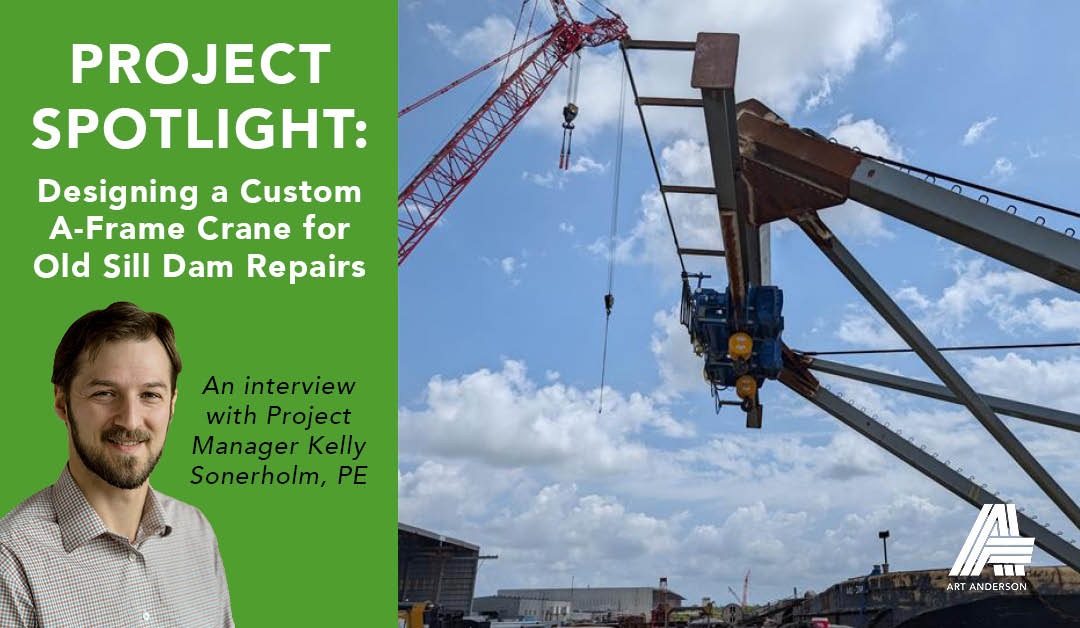
A conversation between Jenny Weitz, Marketing Coordinator, and Kelly Sonerholm, Naval Architect and Project Manager about an A-Frame Crane Design and Barge Stability for performing dam repairs.
Jenny: Kelly, can you start by giving us an overview of the Old Sill Dam project and what our team was asked to do?
Kelly: The Old Sill Dam project was an interesting project! Our client, McMillen, asked us to produce a design for a novel lifting apparatus that was limited by both overhead clearance and space within an old flow control structure.
We chose an A-Frame crane design to be mounted on a modular barge that could be inserted into the spillway to safely remove the aging spillway components and install new components. The location has been the subject of flow control between the Mississippi River and adjacent rivers for hundreds of years now, and it is important for maintaining navigable waterways.
Jenny: What did the project look like at the beginning, and how did it evolve over time?
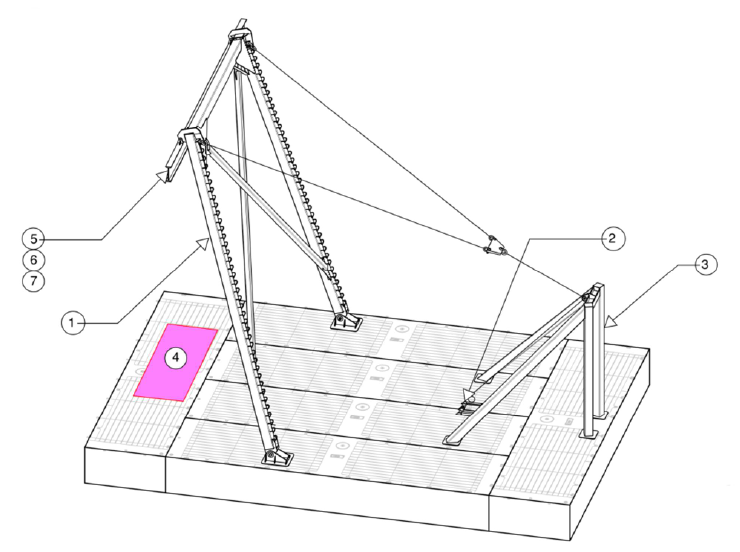
Final design of the A-Frame Crane on modular barge.
Kelly: Initially we were asked to produce a barge lifting apparatus to lift certain specific structures into and out of the spillway. This resulted in a custom A‑frame crane to be installed on a 60‑foot by 60‑foot by 7‑foot modular barge. As the project progressed, McMillen realized the value of the system beyond that one repair effort. The scope expanded to ensure the crane could be reused for future work, which meant revisiting and strengthening the design criteria and performing additional stability analyses.
This project evolution added complexity but ultimately resulted in a more robust and flexible solution that would be ready for McMillen to use on a wide range of other repair operations.
Jenny: From an engineering standpoint, what made this project especially challenging?
Kelly: There were several interrelated aspects that increased complexity. As mentioned, McMillen ultimately desired a reusable platform that would be capable performing multiple tasks. This changed the project objective slightly from accomplishing a single purpose to optimizing the design to accomplish a broader range of lifts. Stability/weight, strength, and overall size were the limiting factors, so after we confirmed that the platform could accomplish the job at hand, we optimized for the capabilities considering all these limits simultaneously.
We were also requested to provide operating instructions which could be presented to a new operator so that they could understand how to use the platform in entirely new scenarios, so we had to consider the possibility of operator error and how to prevent it. We considered how to prevent adverse loading with design decisions rather than rely on operators to understand how to prevent unsafe conditions.
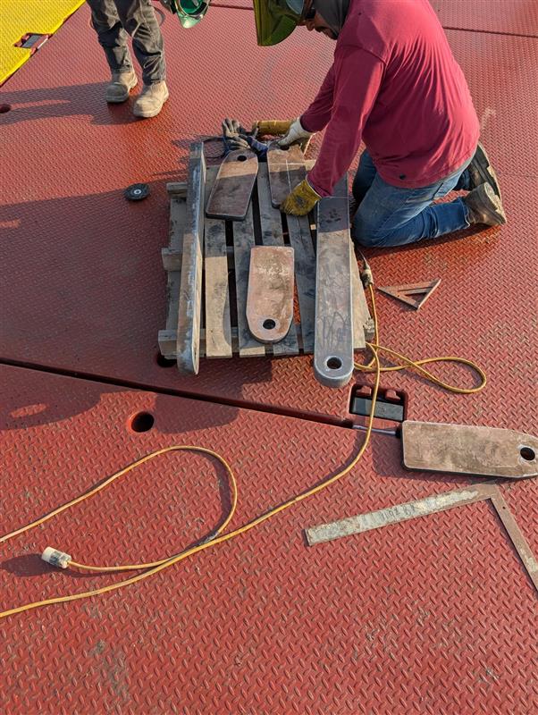
The shipyard fabricated metal linkages to lower the position of the spreader bar on which the electric winches were carried. This prevented contact between the winch and the A-frame when hoisting.
Jenny: Can you talk more about the structural design work your team performed?
Kelly: Our structural scope included selecting and sizing all major A‑frame components—the frame members themselves, the hoist mast, hinge pins, the A‑frame rests, and the spreader which carried the winches. We also calculated maximum tensions in the hoist lines and designed the foundations for the A‑frame, hoist mast, and winch systems. We used Finite Element Analysis (FEA) and beam element based structural analysis software to verify the more complex elements, in addition to hand calculations for elements under simple loading.
Jenny: Stability analysis seems like a major part of this project. What did that involve?
Kelly: Stability is always a crucial consideration in barge lifting design projects. While this project was not necessarily more complex than other types of stability analysis, optimization of the capacity creates complexity. We determine limitations and allow operation up to the limits of the barges stability, including sufficient margin for error, and this requires an understanding of all of the ways that the barge will respond to loading, adverse weather, current, and the possibility for accidental loading outside of the prescribed limits.
In addition to the primary crane barge, there were three additional modular barges McMillen used for staging materials. Each had different dimensions—ranging from 50 by 20 feet up to 70 by 20 feet. We evaluated stability for up to five different lift cases on the downstream side of the dam and performed additional analyses for another McMillen barge that was carrying a crawler crane. All of this was analyzed using General Hydrostatics (GHS), which is an industry‑standard tool for hydrostatic and stability analysis.
Jenny: How did regulatory requirements shape the analysis?
Kelly: Regulations played a major role. We evaluated barge and lift stability against USACE EM 385‑1‑1 Crane Safety Criteria as well as 46 CFR 28.545, which addresses intact stability when lifting gear is in use. Which standards apply depend widely on where the work is to be performed as different regulatory agencies have rules that apply by state, site, or application. They define acceptable risk levels.
Our analyses demonstrated that the planned lifting operations were stable and compliant across all the configurations we evaluated. The goal was also to provide a platform that would be allowable to use under other possible regulatory jurisdictions.
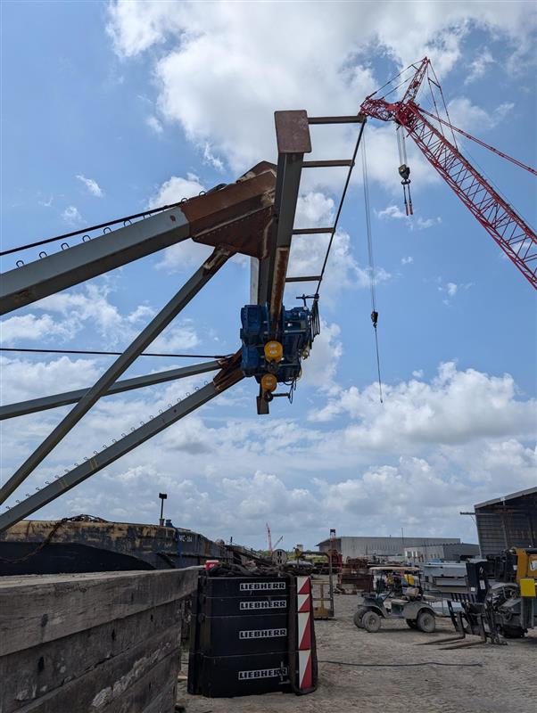
The initial electric winch size was larger than anticipated and came into contact with the A-frame when hoisted.
Jenny: The scope sounds extensive. How did the project manage changes along the way?
Kelly: Like many complex projects, this one evolved significantly. McMillen is a very dynamic company, and their needs for support on new projects expanded during the period of performance for the initial work. Over the course of the work, there were more than ten change orders to address expanded scope, new lift scenarios, and operational adjustments. Clear communication and documentation were key to keeping things moving while maintaining safety and technical rigor.
Jenny: Looking back, what stands out to you most about this project?
Kelly: The thing that stands out to me the most is how flexible the expectations are for us in supporting a construction company such as McMillen. This makes the work interesting but also challenging from a project management perspective. Fortunately, despite the moving target, working with McMillen was a great experience because they are equally flexible and understanding of the challenges. My favorite type of work is when both customer and engineer are focused on getting work done with real world impacts, and this project definitely falls under that category. The technical aspect and interrelation of the aspects of the design are also interesting, and I love seeing it all come together to help our client achieve success.
About Kelly
 Kelly is a naval architect with 20 years of experience. He has provided support for clients including U.S. Navy, U.S. Coast Guard, Alaska Marine Highway System (AMHS), Washington State Ferries (WSF) and Manson. During his career, Kelly has provided detailed engineering system designs and has led production support for vessels.